
Orville let us know yesterday he needed the hold-down locations. I was a little surprised as I thought they had to fill the first 12″ wide courses (before the 8″ ones) but I guess they do it all at once. So it turns out they are almost done with the block. I believe the small openings at the base of the wall are there to show the “cells” or hollowed cores of the block are indeed filled with concrete. I’m not sure how else one could tell [it turns out they do this when they want to exceed 4′ in height- they’ll put a 2×6 against it to contain the ooze when poured].

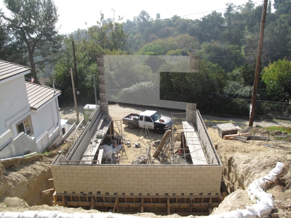
Diagonal View From Above
The top course in back here needs about 3″ more of height1, so they’ll cast that top bit with a board form fastened at each side of the 8″ block wall. A simple trick but I always enjoy the way perspective can “square off” the rhomboid.

View From Above
This level is 5 1/2″ beneath the floor joists,or just under 2′ from the finished doorstep (which will be in this right rear corner). I’m looking forward to this view of the changing colors of the canyon.
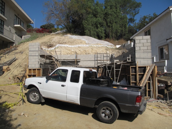
A little mockup to guesstimate the relative wire height, based on the blocks:
Telephone Wires Across Facade
My wife and I spoke about these over the weekend while realizing it may not be possible to bury the power lines. Based on where our neighbor’s feed comes in between our two houses, re-routing to their box from their west property line might be too much work. It looks like these telephone lines, though, don’t need to be here. They could be buried in the road. If they’re out of our eye-line from that first deck (as they appear to be within the upper balcony rail) we may not bother trying. It seems like a lot of this, stray lines that truly should go away, are focused on to an extraordinary degree while you’re putting something together. After, they fade into whatever visual static we habitually ignore.
Here’s what it looks like head on:
Street View

Diagonal View from Street
Another quick sketch showing this as base to the rest of the facade wall:

Sketch of Facade Wall
The dining table will be in this window, but the view will be blocked from here by the projecting balcony. The shaded triangle to the left is the 8′ cantilever for this “porch”. In reducing the plan to the minimum at the basement it became clear this cantilever and the one out back above would give the extra space we’d need. I tend to think porches and balconies seen from within amplify the scale of the space more than they would if the dimension space was incorporated within the same room. It’s probably a bit the added factor of the glass plane between, and not a simple a+b>(a+b). Of course. thanks algebra.
Hold-Downs
The hold-downs are fasteners to secure the ends of the shearwall from uplifting/delaminating from the foundation. Once I got what they were talking about I sent this on to the engineer to confirm their specs- these are stock items but their serial numbers change frequently enough that the callout on the detail sheet was obsolete.

Extract of Structural Framing Plan
I’ve called out the three on the plan whose attachment needs to be fixed. #4 is in midair over the garage opening and will attach to the Timberstrand LSL beam which spans it.
So I expect Luis and Co. will have the threaded rod for the hold downs installed and we’ll be able to get our structural inspection tomorrow. With bang-bang timing we’d be able to both get the city OK and then pour the cells of the block Friday. We can only hope.
footnote
1They’re very conscientious, Orville pointed out on the phone this AM it seemed to him to be 1″ off from where they planned and volunteered the forming idea vs. cutting block- I think that may have been at a different spot on the perimeter. This change from block to poured will look better at the back, where a trench drain will abut this now smooth stripe.
